FRS Unichip R&D Project
We’ve devoted the final quarter of 2012 to wrap up testing and development of our Unichip Plug ‘n Play kit for the MY13 SCION FR-S and have been shipping kits since about mid-November. Feedback has been great and the international Unichip tuning community is also getting in on the act. The kit has thus far received a warm welcome from all: Ten minute installation, power throughout the rpm band, custom tunable… Here’s a short summary of how the project went.
Getting started
Although we’ve used a number of cars for this project, we need to give props to one car’s owner specifically – Quincy wanted to get involved with the R&D portion of the project and drove down from Seattle to give us his for some development and custom tuning… gotta’ love guys with gasoline in their veins! He’s a drift enthusiast and serves in the military. He’s about to head out… be safe Dude. For his enthusiasm, his car gets top billing…
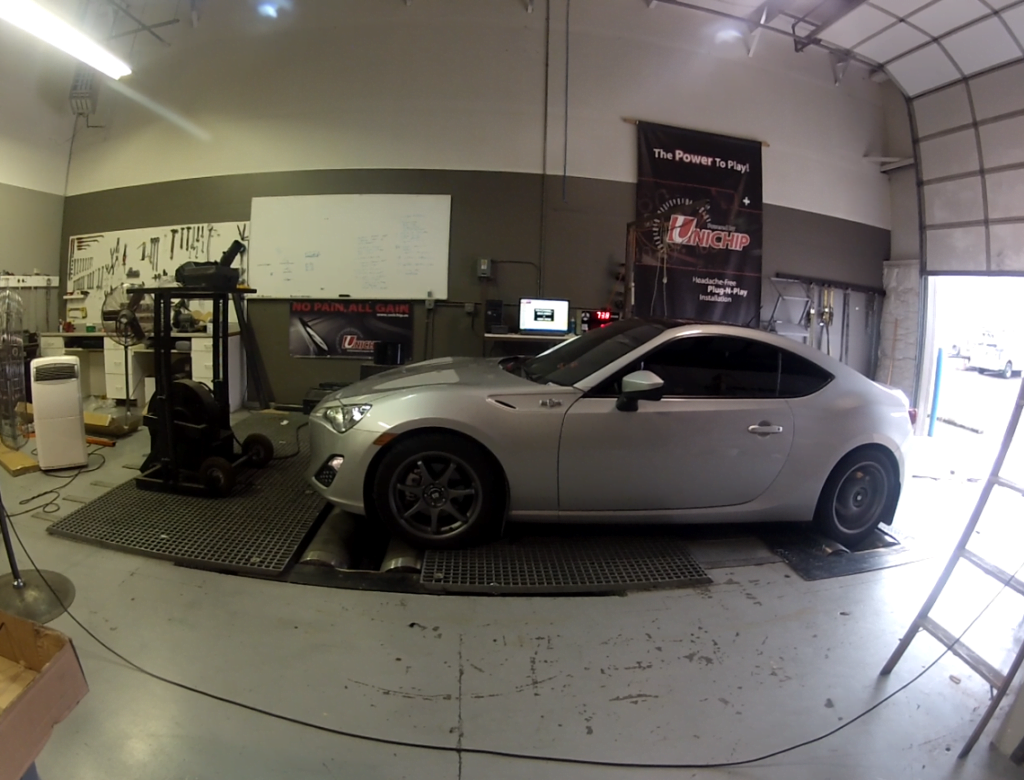
Quincy’s ride on the Rollers
Since this is the first project we’re posting, we’ll get a little more in depth than with the others we talk about… in most fundamental ways, all project follow the same sequence and steps. As with all projects, the first step is getting a car to see if the project is feasible.
Feasibility testing
To be feasible from a production perspective, we have to determine the –
– Electrical schematic so we can wire in the Unichip to ensure it becomes seamlessly integrated into the OE electrical system. Hopefully there’s an OE schematic available and all we have to do is pin-out the wires we’re interested in to verify the schematic… with the FR-S that was exactly the case and we’re off to the next step.
– Signal analysis so we can configure the Unichip to correctly communicate with the OEM computer. Because the Unichip is completely programmable, you can take a Unichip that’s been running in a C5 Corvette and reprogram it to run in whatever else you want… in this case the FR-S. The signals in those two applications look very different, but again drawing on our 25+ years’ experience tuning Toyota’s, the Unichip was already set up to work with all of the FR-S’s signals so this step is as simple as selecting the appropriate options in the Unichip software Map Setup pages.
– The final preliminary task is looking at the connectors to ensure they’re either available for purchase or are something we want to make in house. With the FR-S, it’s a mixed bag and we found some available for purchase and others we can make in our own factories. Interestingly, despite the engine being Subaru, the sensors (MAF, Crank & TPS are all through & through Toyota).
With the production feasibility box checked “yes,” now the car can be instrumented and tuning can start.
Preliminary tuning
Once the Unichip is electrically connected and communicating, the next step is seeing how much room the factory left in their fueling and timing curves and how far we can move those values within the limitations of the hardware like injectors, etc… At this point, we’re not yet tuning for power per se, just seeing how far we can move things what the factory computer thinks about those changes. Although in many respects, an Otto-cycle gasoline engine is an Otto-cycle gasoline engine, how the OE effects control can and does vary between manufacturers and, sometimes, between vehicle types.
With the FR-S, we found some pretty forgiving factory programming that happily accepted changes… just want a tuner wants to see!
Finally, its dyno time to see what sort of numbers our changes put down. Stay tuned…
Dyno testing
With the preliminary testing done, it’s time to strap down the car and see what sort of changes we can effect by moving the timing and fueling values around. As always, we start with a bone stock car and explore “the envelope” by seeing how far we can go and then some…
… fuel first… how rich is the car at full throttle?
… what happens when we lean it out?
… what happens when we lean it out more?
… where does the power peak and where does it fall off?
… now ignition timing… how much additional timing will the car accept before power peaks and falls off?
FRS raw data and multiple runs
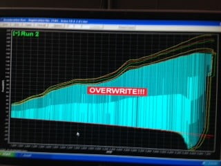
Because the car has to cool down between runs – only runs with the same temperatures are really apples to apples comparison, the basic tuning and testing takes pretty much all day but in the end, the car behaved exactly as expected and returned some pretty nice results.
Bolt-on testing
The next step in all of our testing is putting various bolt-on parts onto the vehicle and building unique calibrations for each of the combinations… that is a Brand X CAI, a Brand X CAI and a CatB exhaust, a Brand X CAI, headers, and a CatB exhaust. Then we pull all those off and do it again with Brand Y, then Brand Z, etc…
We don’t do all that work because it’s fun putting parts on and taking them back off… the calibrations for the different combinations look very different.
Typical results
Once correctly tuned, all combinations end up pretty close – not the case when not tuned! – so for discussion purposes, here are a couple of screen shots from the dyno computer with an Injen CAI on the car… first Torque…
FRS with Injen CAI – Torque
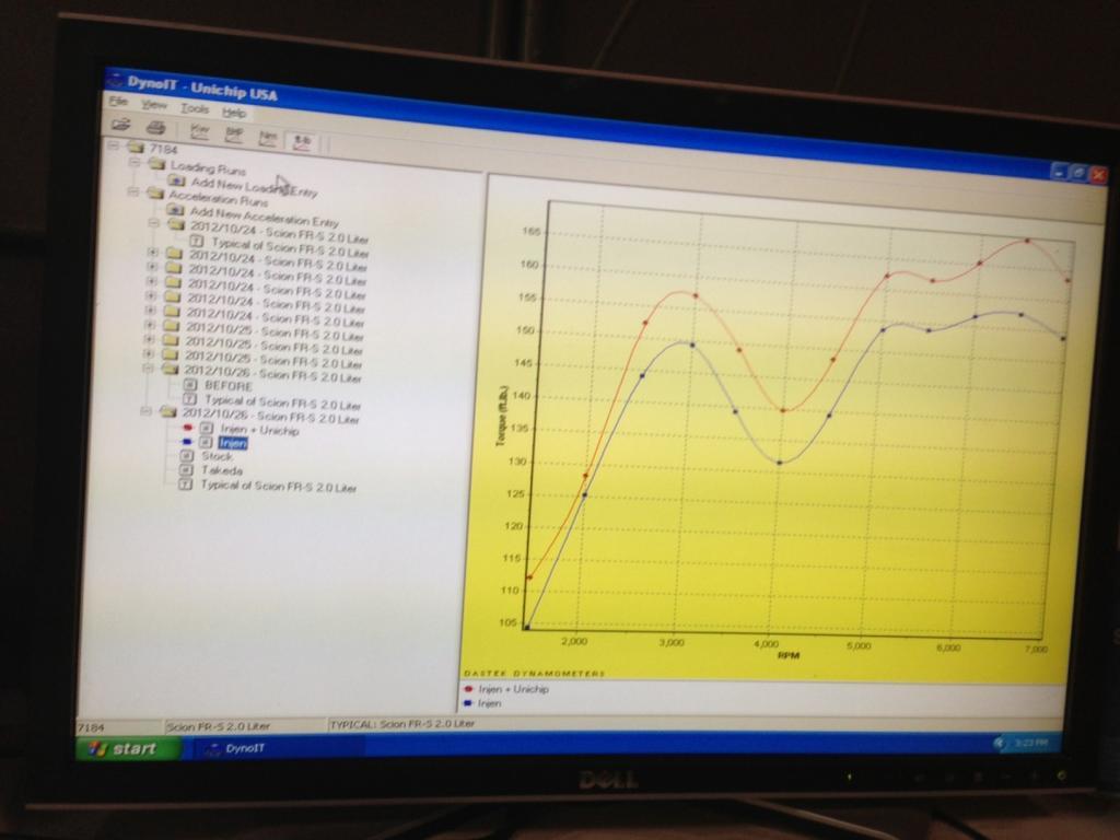
The two lines on the chart both show the FRS with an Injen CAI, same dyno, same temperatures, etc… the only difference is that the blue line is torque without the Unichip and the red line is torque with the Unichip. As you can see, and as expected from the preliminary testing, there’s a really nice gain everywhere… if it’s a little hard to see, the peak gain is from 156 lb-ft to 170 lb-ft. Don’t let the big dip in the middle throw you for a loop… that’s the VVTi low speed and high speed cams and is all about the engine’s volumetric efficiency not tuning.
… next, bhp…
FRS with Injen CAI – bhp
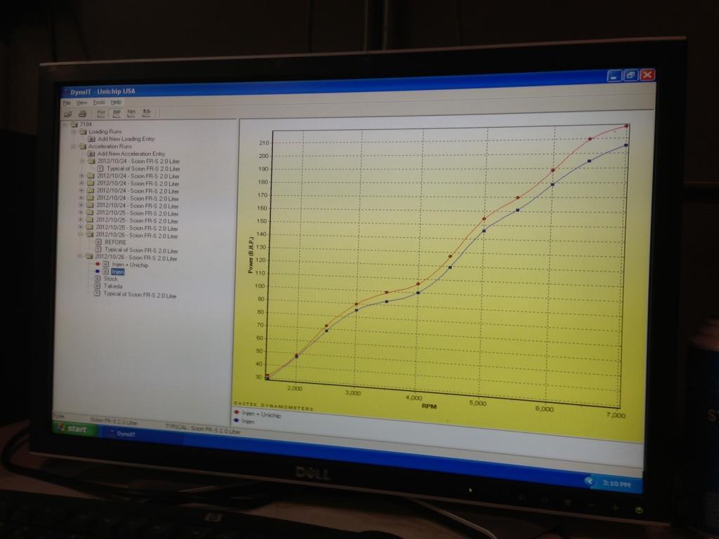
Once again, gains everywhere with the peak gain going from about 205 without the Unichip to 218.
Third party testing…
Several early adopters headed to the dyno to check things out after installing their Unichips and consistently got results in line with what we found. Obviously, dyno’s differ and comparing somebody’s car in Denver to another guy’s in Miami isn’t really valid because each dyno is a different machine, settings are different, temperatures are different, altitudes are different, etc… but comparing the average percentage change from some “before” runs to the average of some “after” runs is a decent test and the results should be pretty consistent… and that’s just what we’re hearing.
Here’s a dyno sheet sent in by a customer who went to his dyno shop for some pulls. The car’s mod’s are an Injen CAI, a catback exhaust, and the Unichip. The customer has a Flux2 Display with three performance maps loaded and the three runs show whatever his dyno guy called “good” at the end of the session for each of the three maps… lowest to highest are the low octane map, the midgrade fuel map, and the premium grade fuel map.
Since this was on a Dynojet, we know the numbers are at the wheels but we don’t have a lot more information about temperature, fuel used, etc… The customer told us there’s one pull for each of the three maps with the green trace being the high octane map and the only difference between the runs is flipping a switch… assuming the IAT was controlled reasonably well. Assuming a nominal 15% drive train loss, 180.93 bhp at the wheels means 212.8 at the flywheel which is a couple of bhp more than we found on our dyno but certainly reasonable given that this is a different dyno and a different day.
Designing a harness…
Our design goals for each new harness is reliability, installation simplicity, installation simplicity, some more installation simplicity, and above all it’s got to be simple to install! Since we’ve already identified the signals we want, our challenge is finding the most reliable and easily accessible points in the factory electrical system to pick up those signals so we can manipulate them.
For the FR-S, we tie into the three sensors using male/female connectors that are easily accessible from the top side of the engine… here’s the harness…
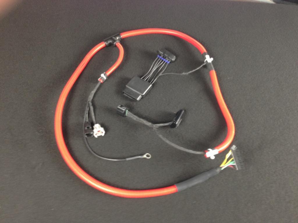
… can’t get much simpler. Connect to the throttle body, to the crank position sensor, and to the MAF and everything’s integrated. Plug into the Unichip and you’re rockin’…Click
for a PDF of the instructions to see what it looks like in the engine bay.
https://www.unichip.us/wp-content/uploads/2019/12/2620052.0-FRS-2.0-MY13-on.pdf

Just the right spot…
We found a perfect spot to mount the Flux2 Display…attach it to the driver’s side fixed quarter window and it looks like of OEM installation. It’s within easy reach, doesn’t block any sight line outside of the car, and with a quick flick of your eyes you can see whatever data you want to call up… pretty slick. Right now Unichip is, once again, in the leading position of being able to provide a top-class tuning solution, with an in-car display/controller. Both the Unichip & the display are forced induction ready.
Takin’ it to the streets…
The dyno is a great place to get started. Very controlled, very stable, but unfortunately it’s not really the same as the real world. Temperatures and air pressures are different, vehicles often behave differently when only a pair of wheels are spinning, etc… Invariably, we find that when we hit the asphalt, the calibration we built will get tweaked to account for the differences… it’s one of the most important parts of building a quality calibration you can count on for a Plug&Play solution… it also doesn’t suck in the middle of your work day…
Unichip installation bracket…
So one of the great things about being sister companies with two of the largest aftermarket plastics manufacturers in the US is you can get some pretty sweet custom stuff manufactured. One of the bad things is that sometimes you have to wait for an opening in your sister company’s schedule. The good news is that we’ve finally made it to the head of the line!
Since the beginning of the FR-S project, the intent was to produce a finished bracket to hold the Unichip in place that holds the Unichip securely, looks good, can be easily removed, and makes no permanent changes to anything.
Yesterday, the design was approved and early next week the tool will be built to put out the first production part…
The car’s fuse box cover is shown in blue and the Unichip in white. The mounting bracket will be in a rubbery black plastic and will attach to the fuse box with double sided tape and a clip that snaps in place… the Unichip attaches to the bracket with two stainless machine screws and Nylock nuts.
The plastic is robust and heat cycle resistant so it won’t crack or get brittle over time… once we have the prototypes in hand, we’ll do some testing and begin including the bracket as part of the kit. For those early adopters already running a kit on their cars, we’ll provide a bracket at no cost.
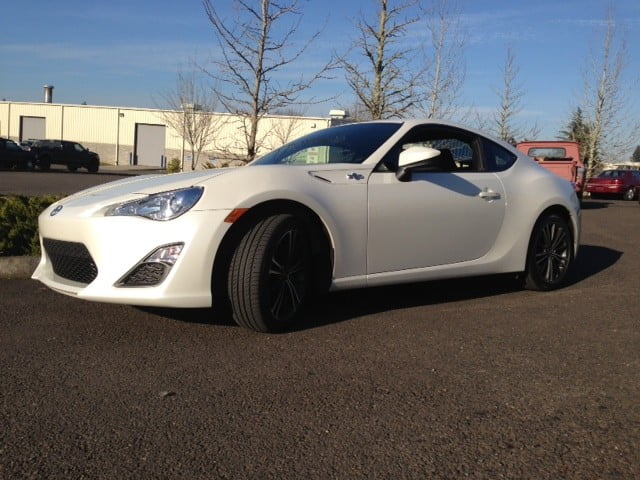
New addition…
One hour old and ready to join the R&D team. Busy weekend ahead with breakin miles and the next time you see her, she’ll be on the dyno…
Launch Control…
For the MT owners, we finalized both launch control and flat foot shifting working with an extremely experienced tuner. Like a standard launch control, press down the clutch and push the accelerator pedal to the floor and the engine accelerates to the “capture” rpm and stabilizes… nominally 5,000 rpm but the specific rpm you want it programmable.
Similarly, with flat foot shifting, shift times accelerating hard through the gears is greatly improved… punch the accelerator pedal to the floor and leave it there. When you press down the clutch, the engine maintains a target rpm rather than falling as it does in a standard shift. When you’ve changed the gear and release the clutch, the engine is already on the high speed cam and ready to pull.
Launch control and flat foot shifting are currently being offered by Unichip tuners like Unichip Whole sale…http://www.unichipwholesale.com/product/2013-subaru-brz-2-0l-launch-control-upgrade/
End User Mapping…
We have also posted a large map library for the FT86 for various bolt-on configurations, all grades of pump fuel, and individual vehicle variations.
As with each vehicle we make a kit for, we get all of the popular parts, put them on our test mule, and build unique calibrations for them. The maps make “families” centered around the intake system mounted on the car since the intake on a normally aspirated vehicle most effects the calibration. We build a calibration for the intake alone, the intake and exhaust modifications, and the intake, headers, and exhaust modifications. For the FT86, we’ve completed maps for the Stock airbox as well as the AEM, AiRaid, GReddy, Injen, Perrin, and Takeda intake systems and have the TRD and K&N systems ready to go onto the car next.
For each one of those bolt-on configurations, we build “Standard” maps for low octane, midgrade, and premium pump gas. The Standard maps will generally be the best fit for most vehicles and an excellent starting point for all vehicles with those parts. To accommodate minor vehicle-to-vehicle variations, we also make maps that run slightly more fuel (called “Fuel In” maps and denoted by a “+” in the map name) for vehicles that run slightly lean without the Unichip and “Fuel Out” maps (denoted by a “-” in the map name) for vehicles that run slightly rich without the Unichip.
We also create maps that run slightly more ignition timing (Timing In and again denoted by a “+” in the map name) for vehicles that will accept the timing and a Timing Out map (“-” in the map name) for vehicles especially sensitive to timing.
The maps posted to the online user data base are combinations of all of the above so you can easily find the maps that are best for your car. Having a Flux2 display makes testing maps a lot of fun because you can load 5 at a time & go out on the road to see which ones work best..
New parts…
We’re just completing the AEM CAI map family and have received the new TRD CAI for the car which will go on next.